mohitsinghi35@gmail.com - GST NO. : 06AAACH5844E1ZT
- Send Email
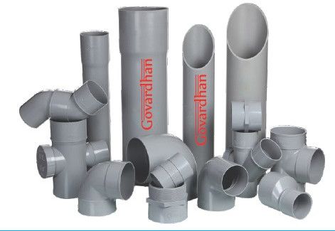
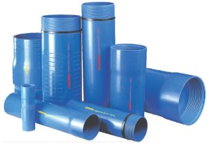
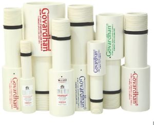
| Business Type | Manufacturer, Exporter, Supplier, Retailer |
| Size | 20 mm to 315 mm |
| The thumb rule principle is | 1 kgf/cm=10 m of water column |
| Range | 2.5 kgf/cm2, 4 kgf/cm2, 6 kgf/cm2, 10 kgf/cm2 |
| Click to view more | |
Product Details
Properties :
- Co-efficient of linear expansion : 5.4 x 10 mm/m/ C
- Specific gravity : 1.41-1.46 gm/cm
- Impact Strength : Complies with IS : 4985 2000
- Electrical Resistance : 10 ohm-cm
- Vicat softening point : 80 C
- Tensile Strength : 500-550 kg/cm
Applications
- Industrial ducting
- Building Installations
- Sewerage & drainage
- Gas & Oil supply lines
- For slurry disposal lines
- Air conditioning ducting
- Rural & urban water supply
- Agriculture & Irrigation System
- Sewerage & industrial effluent disposal
- Power and telecommunication cable ducting
- Discharge pipes for hospitals & residential buildings
- Portable water supplies and drinking water supplies
- Plumbing and drainage systems in the dwelling
- houses
- Lift Irrigation, Bore wells etc. by both Govt. & Farmers
Installation
While designing the pipe line system, the level and depth of the trench is calculated depending on factor such as the terrain and function of the pipeline. Excavation and pipe laying must take place simultaneously, as leaving trenches open for too long, makes them unsuitable for use. A fine layer of sand should be spread on the trench-bed, to avoid mechanical damage arising due to the pipe coming in direct contact with the solid bed. Like wise, it is also recommended to put a fine layer of fine sand on the top of the pipe before filling and carrying the soil to cover the trench. As pipe laying advances, trenches must be backfilled immediately. The pipe joints however should be left exposed till after the pipe line s stem has been tested. The maximum width of the trench must be equal to the pipe diameter plus 300 mm. At the crown of the pipe, the trench width must not exceed the pipe diameter plus 600 mm.
.
Design
1. Basic Parameters
1.1 Water Quantity (Q) : the amount of water required to irrigate the land, considering crop pattern and irrigation frequency (in liters/second)
1.2 Length of Pipe line (L) : The length of the pipe, from source to destination of discharge point (in meters)
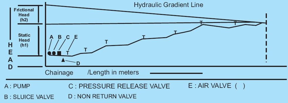
1.3 Static Head (H) : The level difference between the lowest and the highest level of the pipe (in meters)
Selection of Pipe
For best efficiency and optimum output, use the flow chart available below shown. It is suggested that one should select the pipe size at an inter section of velocity 1 meter/second and discharge (litre/second). Frictional losses (h2) are also to be taken care of as shown in the diagram.
.
Frictional losses can also be calculated by empirical Hazen Williams formula i.e :
V = 4.567 X 10 X C X D X S
Where V = Velocity of fluid flowing through the pipe
D = Internal Diameter of the pipe
C = Hazen Williams co-eff. for PVC (150)
S = Hydraulic Gradient
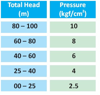
Guideline for pressure class selection
The total head (H) acting on the pipe area on a particular point is calculated as
H = h1+h2 + 10% (h1+h2) (in meter/km.)
Where 10% (h1+h2) is the safety factor for losses in valves and fittings
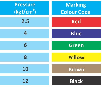
The selection of high pressure class can then be done from
the table :
Selection of Pump
The formula is : HP of the pump = Q X H/75 X h
Where s = Efficiency of the pump in % (i.e. 65%)
From the basis of these calculations suitable pump can be procured from the market.
Selection and installation of the air valves
An air valve in the pipe line, functions the way are nose does. This is one of most critical - yet often neglected components in an uPVC Pipe line.
Since air is compressible in nature, it tends to accumulate in the pipe line. A non-functional air valve causes the accumulated air to generate very high localized pressure. This can not be read on a conventional pressure gauge. To avoid such an occurence, air valve should be installed at distances of 300 to 400 meters at all peak points through out the pipe line.
Such air valves can be easily procured from the market by having a proper selection of material
available.
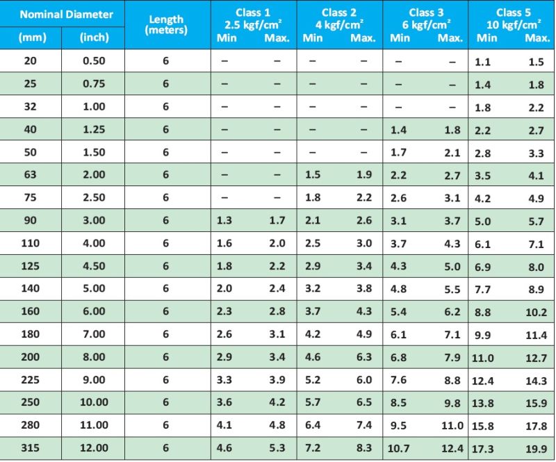
D I M E N S I O N A S P E R I S 4 9 8 5 : 2 0 0 0
Looking for "UPVC Agricultural Pipes" ?
Explore More Products


